

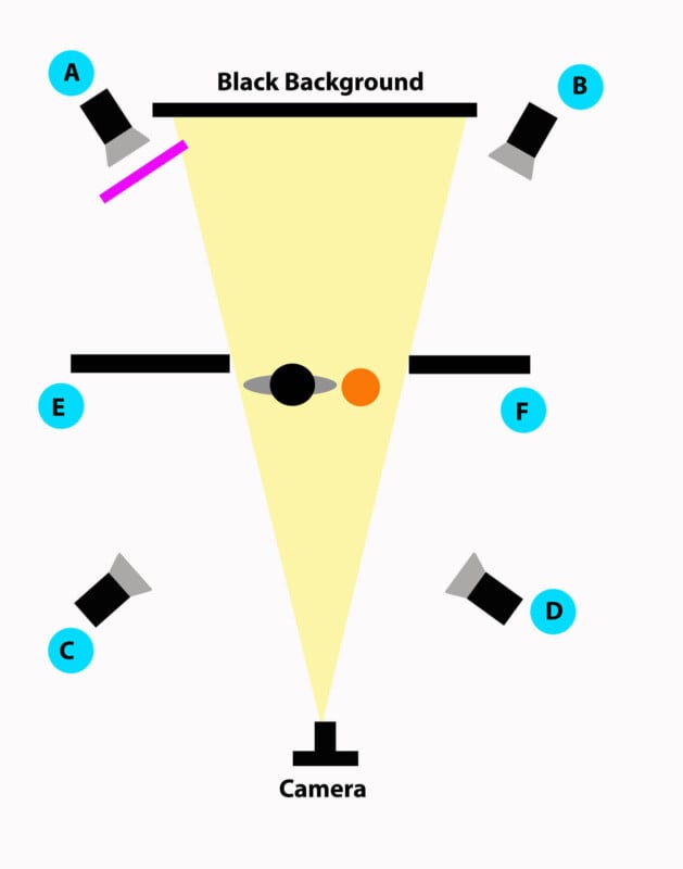
The high-speed class at Rochester Institute of Technology learns Arduino programming and some simple circuits as an introduction on triggering high-speed flashes in complicated situations. One of the easiest high-speed events to study is a balloon popping. This simple event is also one of the safest high-speed events too.
To add more interest to the balloons as they are popping, a few milliliters of water is added to the balloon before it is inflated. The students pop the balloon by using a sharp tack to break the skin. As the balloon pops the internal pressure drops causing the water vapor to form a cloud for a few thousandths of a second. The idea is that the students will take a picture as the balloon is popping to show the cloud. The students typically enjoy this activity quite a bit.


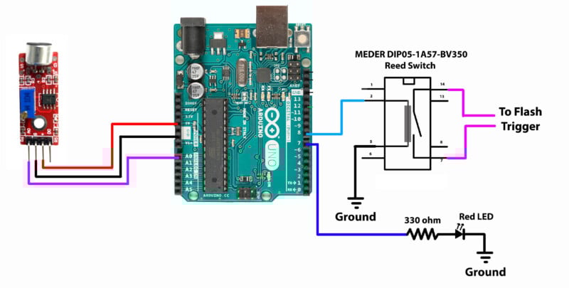
The total cost of the electronic involves an Arduino microprocessor, a sound trigger, and a reed switch is around 20 dollars with the most expensive component being the Arduino microprocessor. In the lab we often use the 640 Einstein flash on the 1/256 power setting which the students measure to be 195 microsecond duration.

Not all sound detectors are the same. Above are two common types, and each has different levels of sensitivities. Each detector has an adjustable resistor that controls the output pin’s trigger level (labeled DO on the red unit and OUT on the blue unit). The digital out pins on these units send the output voltage to a logic high or 5 Volts when a sound is detected. The trigger level of the sound is set by the resistor on the amplifier. After testing, the red unit was found to be the most sensitive to low levels of sound. As the detectors change quite often, each device needs to be tested.
Above the red detector has an extra pin that supplies an analog output. This output is a variable voltage ranging from 0 to 5 volts. The Arduino uses a 10-bit analog converter that maps the voltage to integers from 0 to 1023 in values. The resulting integer values are used by the Arduino code to trigger the flash when the sound level goes above the ambient level. Since this pin supplies a changing voltage in response to different sound levels it is the easiest to program to trigger at different sound levels.
To test the response of the microphone I use the following sample code:
/*
Analog input, to trigger a flash by a reed switch
Reads an analog input pin, prints the results to the Serial Monitor.
Ted Kinsman [email protected]
*/
// These constants won’t change. They’re used to give names to the pins used:
const int analogInPin = A0; // Analog input pin that the potentiometer is attached to
int sensorValue = 0; // variable to set the value read from the A0 (analog pin)
void setup() {
pinMode (analogInPin, INPUT); //pin A0 is an analog input
Serial.begin(9600);// initialize serial communications at 9600 bps:
}
void loop() {
sensorValue = analogRead(analogInPin);// read the analog in value:
// print the results to the Serial Monitor:
Serial.print(“Sensor Value = “);
Serial.println(sensorValue);
delay (100); // this delays the loop by 100ms and slows the text display
}
This program can display the output to the serial port, and the results are displayed as text.
15:26:31.008 -> Sensor Value = 72
15:26:31.107 -> Sensor Value = 72
15:26:31.204 -> Sensor Value = 71
15:26:31.303 -> Sensor Value = 71
15:26:31.402 -> Sensor Value = 71
15:26:31.500 -> Sensor Value = 72
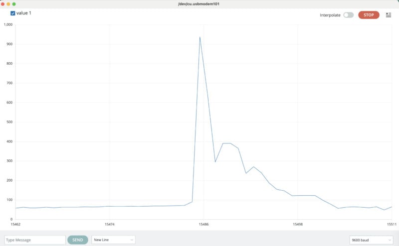
The serial plotter can be used to display the data in a graphical format and is found under the tools directory.

Below is the finished program:
/*
2024-Sound-TriggerA.ino
Ted Kinsman October 7, 2024
Analog input, to trigger a flash by an isolating reed switch
Reads an analog input pin, prints the results to the Serial Monitor.
Turn the serial port off when running for photography for speed.
Camera is set to bulb setting.
*/
// These constants won’t change. They’re used to give names to the pins used:
const int analogInPin = A0; // Analog input pin that the potentiometer is attached to
const int LED7 = 7; // a RED LED is on pin 7 this is the “Busy Signal”
const int FlashTrigger= 8; //pin to trigger the flash via reed switch
int sensorValue = 0; // variable to set the value read from the A0 (analog pin)
void setup() {
pinMode (analogInPin, INPUT); //pin A0 is an analog input
pinMode (LED7, OUTPUT ); //LED7 is an output
pinMode (FlashTrigger, OUTPUT); //flash trigger is connected to the reed switch is an output
// initialize serial communications at 9600 bps:
Serial.begin(9600);
}
void loop() {
// read the analog in value:
sensorValue = analogRead(analogInPin); //read the A0 pin and write value to “sensorValue”
if (sensorValue >=80){
delay(0); //if the flash is set off too fast increase this time in milliseconds
digitalWrite (FlashTrigger, HIGH); //turn on pin to trigger the flash
digitalWrite (LED7, HIGH); // turn on led on pin 7
delay(1); // delay 1 ms to make a nice trigger pulse
digitalWrite (FlashTrigger, LOW); //turn off pin to trigger the flash
Serial.print(“Sensor Value = “);
Serial.println(sensorValue); //prints trigger value to serial port and does a line return
delay(4000); //four second delay to give the photographer time to close the shutter
digitalWrite (LED7, LOW); // The busy signal – RED led on pin 7 – is turned off
}
}
Note: The use of the serial port and the command “Serial.print” will slow the Arduino down, so it is best to only use the serial port when the high-speed event is over.
Here the flash has been triggered and there is plenty of time to send an analog read value to the serial port.
The RED led here is used to show that the circuit has been triggered, and if the LED is lit the photographer should wait until the LED turns off to proceed with the photoshoot. I call this the circuit “Busy Signal”.
The 4 second wait time after the flash trigger is used to allow the photographer to close the shutter when using the bulb setting on the camera. This delay allows the flash to only fire once on the first loud sound.
The sound sensor has a second pin which is a DO or stands for digital out. To use this pin, the screw potentiometer on the amplifier needs to be adjusted so that a loud sound will send this pin to a +5 volts. I have found many of these detectors to not be particularly sensitive, and the ones I have tested have often failed to trigger on the sound of a popping balloon so over the years I have moved to solely use the detectors that have an analog output and use the code posted above.


About the author: Ted Kinsman is the 2019 recipient of the Schmidt Laureate for outstanding contributions to the progress of biocommunications. Kinsman has worked as an optical engineer, a physicist, and a physics instructor before joining the Photographic Sciences Dept. at RIT. His work has appeared on The Discovery Channel, Crime Scene Investigations (CSI), The X-Files, South Park, The Tyra Banks Show, and The Frozen Planet series. Kinsman is currently an Associate Professor in the School of Photographic Arts and Sciences (SPAS) where he teaches Photographic Instrumentation, Scanning Electron Microscopy, and High-Speed Imaging.